Choosing the Right Lighting for High Speed Inspection
Jun 30, 2019
Choosing the Right Lighting for High Speed Inspection

Lighting and timing are key factors when measuring parts in high speed motion. By using short bursts of high intensity lighting, the vision system effectively freezes the motion for inspection.

Lighting and timing are key factors when measuring parts in high speed motion. By using short bursts of high intensity lighting, the vision system effectively freezes the motion for inspection.
 
Proper lighting is often the determining factor in the success of high speed part inspection. If the timing overlap is off between the stage motion encoder, camera exposure and LED strobe lighting, the result will be dark or blurry images. If the timing between the stage and strobe is not deterministic, the desired feature may shift from image to image, which is a serious problem when measuring the distance between features in different images.
 
Precise synchronization ensures that the camera consistently freezes the image of a moving part at the same location in the image while minimizing pixel blur. By using short bursts of high intensity lighting, the vision system effectively freezes the motion so that the part image appears stationary.
 
Machine vision systems create images by analyzing the reflected light from an object, not by analyzing the object itself. To determine how light will reflect from a part, it’s important to understand the material of the part as well as its size, shape, finish and color. Process speed and the measurement or inspection requirements also determine lighting choices.
Although brighter is often better, the key is to provide sufficient contrast for the features of interest while suppressing the surrounding clutter. Machine vision applications involving image contrasts below 20% present specific challenges, according to Vision Systems Design. In such low contrast applications, even the slightest variation in LED output intensity can have a substantial impact on the performance of the inspection system. Lighting is even more critical in these cases. For example, directional lighting may be used to cast shadows and highlight specific edges.

Starting with the Proposal Process

At DWFritz, PMs are a part of a collaborative multidisciplinary team that guides the project proposal process. From mechanical and electrical engineers to controls software and vision engineers, the company brings more than 45 years of experience building automation equipment. As seasoned professionals with engineering or technical backgrounds, PMs often bring relevant work experience from the same industries as customers.

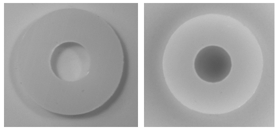
The nylon washer image on the left has poor contrast between the part edges and the white background. The image on the right uses multidirectional lighting to provide better contrast and defined edges


Custom Lighting Solutions
 
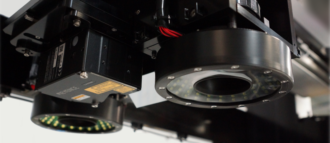
Using proprietary light engines consisting of strobe controllers with multiple channel LED lighting, interconnected cabling and light assemblies, DWFritz’s custom lighting solutions for metrology platforms help manufacturers tackle even the most difficult inspection applications.
 
DWFritz’s strobe controller assembly consists of an LED controller and LED driver printed circuit assembly (PCA) that generates a significant amount of instantaneous power for a specified duration at a set time to illuminate LEDs. Pulsing or strobing the LED array provides high intensity illumination at a short duty cycle with no detrimental impact on the lifespan or performance of the array.
 
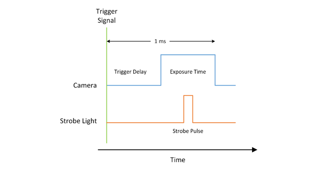
The timing relationship between the camera and strobe controller is critical. These strobe pulses must occur inside the envelope when the camera sensor is exposed. DWFritz vision systems use encoder-based triggering to turn on the LEDs at the right time. Application-specific algorithms use encoder triggers from the stage motion to coordinate individual triggers for the camera, the strobe controller and specific light channels.
This intricate trigger sequence takes place in milliseconds. Leveraging the pulse train from the stage encoder, the sensors in the camera are precisely orchestrated to capture an image. Correspondingly, the strobe controller helps illuminate the part at the precise moment. Multiple images of a part can be captured using a single light and controller by changing the intensity parameters per trigger.

An encoder-based signal triggers the camera to expose its sensor, followed by the strobe light.


Choosing the Right Lighting for the Job
 
A part’s surface optical properties, such as color, finish and transparency, as well as part features like size and shape will determine lighting selection. Measurement, inspection and throughput requirements also play a critical role in identifying illumination schemes.
Before deciding whether to use a backlight, coaxial, dome or ring light, it’s important to analyze whether the lighting will be used in an on-axis or off-axis configuration, according to Photonics.
 
On-axis (bright field) illumination provides even, flat diffuse illumination, which is important when illuminating flat nonreflective surfaces, such as metal, glass and plastic. Dome lights are commonly used as bright field components, while coaxial illuminators are often used as partial bright field components. On-axis configurations also can include spotlights, line lights and ring lights. On highly reflective surfaces, an on-axis light may just provide an image of the light itself.
 
Off-axis (or dark field) lighting reflects much of the incident light away from the camera lens. Edges or scratches on part surfaces reflect the light, while flat, polished surfaces remain dark. In dark field lighting, low angle lighting can illuminate the object from either single or multiple directions to cast shadows for specific edges.
 
Oftentimes different parts and inspections require different illumination angles. The directionality and uniformity of angles affect the appearance of the features. To find the ideal lighting, it helps to analyze the light from the perspective of the region of interest (ROI) on the part.
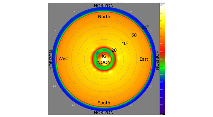
Imagine an ant resting on the center of a stationary part on a metrology platform, just a few millimeters below an LED light array. What would the ant “see” when looking up at the sky? This ant’s eye view illustrates that there is a big difference between illuminating a part with a 45° sunrise light versus a high noon collimated coaxial shot versus a uniform cloudy day dome illumination. In the ant’s eye view, a perfect collimated coaxial light would produce a small spot at high noon. The ideal cloudy day dome light should be uniform from horizon to horizon.
This spherical polar map illustrates the ant’s eye view from the perspective of a part measured using a fisheye lens.

One of the goals of high speed inspection is to achieve the required intensity, uniformity and repeatability in all shots. By choosing the right lighting and ensuring precise synchronization, shot 1 to shot 10 to shot 10 million should be virtually identical.
Learn more about custom lighting solutions available on DWFritz’s non-contact metrology systems.
DWFritz Automation LLC